
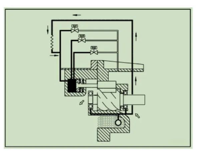
1. Four-stage capacity adjustment principle of screw compressor

The four-stage capacity adjustment system consists of a capacity adjustment slide valve, three normally closed solenoid valves and a set of capacity adjustment hydraulic pistons. The adjustable range is 25% (used when starting or stopping), 50%, 75%, 100% .
The principle is to use the oil pressure piston to push the volume control slide valve. When the load is partial, the volume control slide valve moves to bypass part of the refrigerant gas back to the suction end, so that the refrigerant gas flow rate is reduced to achieve the partial load function. When stopped, the force of the spring makes the piston return to the original state.
When the compressor is running, the oil pressure starts to push the piston, and the positioning of the oil pressure piston is controlled by the action of the solenoid valve, and the solenoid valve is controlled by the water inlet (outlet) temperature switch of the system evaporator. The oil that controls the capacity adjustment piston is sent from the oil storage tank of the casing by means of differential pressure. After passing through the oil filter, a capillary is used to limit the flow and then sent to the hydraulic cylinder. If the oil filter is blocked or the capillary is blocked, the capacity will be blocked. The adjustment system does not operate smoothly or fails. Similarly, if the adjustment solenoid valve fails, a similar situation will also occur.

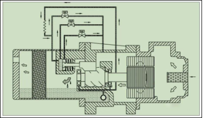
1. 25% start operation
When the compressor is started, the load must be reduced to a minimum to be easy to start. Therefore, when SV1 is actuated, the oil is directly bypassed back to the low-pressure chamber, and the volumetric slide valve has the largest bypass space. At this time, the load is only 25%. After the Y-△ start is completed, the compressor can start to gradually load. Generally, the starting time of 25% load operation is set to about 30 seconds.
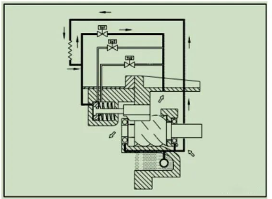

2. 50% load operation
With the execution of the start-up procedure or the set temperature switch action, the SV3 solenoid valve is energized and turned on, and the capacity-adjusting piston moves to the oil circuit bypass port of the SV3 valve, driving the position of the capacity-adjusting slide valve to change, and part of the refrigerant gas passes through the screw The bypass circuit returns to the low-pressure chamber, and the compressor operates at 50% load.
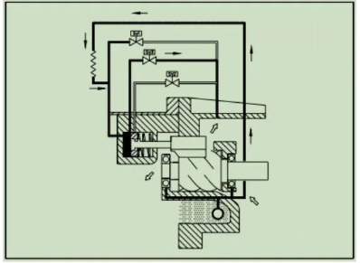
3. 75% load operation
When the system start-up program is executed or the set temperature switch is activated, the signal is sent to the solenoid valve SV2, and SV2 is energized and turned on. Return to the low-pressure side, part of the refrigerant gas returns to the low-pressure chamber from the screw bypass port, the compressor displacement increases (decreases), and the compressor operates at 75% load.
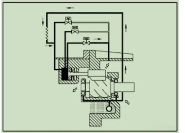

4. 100% full load operation
After the compressor starts up, or the freezing water temperature is higher than the set value, SV1, SV2, and SV3 are not powered, and the oil directly enters the oil pressure cylinder to push the volume adjustment piston forward, and the volume adjustment piston drives the volume adjustment slide valve to move, so that the cooling The agent gas bypass port gradually decreases until the capacity adjustment slide valve is fully pushed to the bottom, at this time the compressor runs at 100% full load.
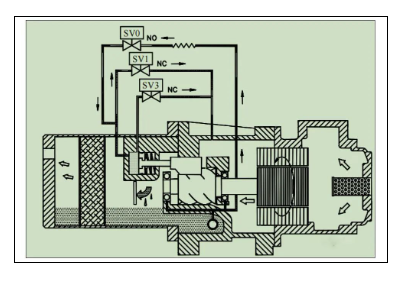
2. Screw compressor stepless capacity adjustment system
The basic principle of the no-stage capacity adjustment system is the same as that of the four-stage capacity adjustment system. The difference lies in the control application of the solenoid valve. The four-stage capacity control uses three normally closed solenoid valves, and the non-stage capacity control uses one normally open solenoid valve and one or two normally closed solenoid valves to control the switching of the solenoid valve. , to decide whether to load or unload the compressor.
1. Capacity adjustment range: 25%~100%.
Utilize a normally closed solenoid valve SV1 (control oil drain passage) to ensure that the compressor starts under the minimum load and a normally open solenoid valve SV0 (control oil inlet passage), control SV1 and SV0 to be energized or not according to load requirements To achieve the effect of controlling capacity adjustment, such stepless capacity adjustment can be continuously controlled between 25% and 100% of the capacity to achieve the function of stable output. The recommended action time of solenoid valve control is about 0.5 to 1 second in pulse form, and can be Adjust according to the actual situation.

2. Capacity adjustment range: 50%~100%
In order to prevent the refrigeration compressor motor from running under low load (25%) for a long time, which may cause the motor temperature to be too high or the expansion valve to be too large to cause liquid compression, the compressor can be adjusted to the minimum capacity when designing the stepless capacity adjustment system. Control above 50% load.
A normally closed solenoid valve SV1 (control oil bypass) is used to ensure that the compressor starts at a minimum load of 25%; in addition, a normally open solenoid valve SV0 (control oil inlet passage) and normally closed solenoid valve SV3 (control oil drain access) to limit the operation of the compressor between 50% and 100%, and control SV0 and SV3 to receive power or not to achieve continuous and stepless control effect of capacity adjustment.
Suggested actuation time for solenoid valve control: about 0.5 to 1 second in the form of a pulse, and adjust it according to the actual situation.
3. Four flow adjustment methods of screw compressor
Various control methods of screw air compressor
There are many factors to consider when selecting the type of screw air compressor. The highest air consumption must be taken into account and a certain margin must be taken into account. However, during daily operation, the air compressor is not always under the rated discharge condition.
According to statistics, the average load of air compressors in China is only about 79% of the rated volume flow rate. It can be seen that the power consumption indicators of rated load conditions and partial load conditions need to be considered when selecting compressors.
All screw air compressors have the function of adjusting the displacement, but the implementation measures are different. Common methods include ON/OFF loading/unloading adjustment, suction throttling, motor frequency conversion, slide valve variable capacity, etc. These adjustment methods can also be flexibly combined to optimize the design.
In the case of a certain energy efficiency of the compressor host, the only way to achieve further energy saving is to optimize the control method from the compressor as a whole, so as to actually achieve comprehensive energy saving effects in the application field of air compressors.
Screw air compressors have a wide range of applications, and it is difficult to find a completely effective control method that is suitable for all occasions. It needs to be comprehensively analyzed according to the actual application situation in order to select the appropriate control method. The following briefly introduces four common control methods including other Main features and uses.

1. ON/OFF loading/unloading control
ON/OFF loading/unloading control is a relatively traditional and simple control method. Its function is to automatically adjust the switch of the compressor inlet valve according to the size of the customer’s gas consumption, so that the compressor is loaded or unloaded to reduce the gas supply. Fluctuations in pressure. In this control there are solenoid valves, intake valves, vent valves and control lines.
When the gas consumption of the customer is equal to or greater than the rated exhaust volume of the unit, the start/unload solenoid valve is in the state of energization and the control pipeline is not conducted. Running under load.
When the customer’s air consumption is less than the rated displacement, the pressure of the compressor pipeline will rise slowly. When the discharge pressure reaches and exceeds the unloading pressure of the unit, the compressor will switch to unloading operation. The start/unload solenoid valve is in the power-off state to control the conduction of the pipeline, and one way is to close the intake valve; the other way is to open the vent valve to release the pressure in the oil-gas separation tank until the internal pressure of the oil-gas separator tank is stable (usually 0.2~0.4MPa), at this time the unit will operate under lower back pressure and keep no-load status.

When the customer’s gas consumption increases and the pipeline pressure drops to the specified value, the unit will continue to load and run. At this time, the start/unload solenoid valve is energized, the control pipeline is not conducted, and the intake valve of the machine head maintains the maximum opening under the action of suction vacuum. In this way, the machine repeatedly loads and unloads according to the change of gas consumption at the user end. The main feature of the loading/unloading control method is that the intake valve of the main engine has only two states: fully open and fully closed, and the operating state of the machine only has three states: loading, unloading, and automatic shutdown.
For customers, more compressed air is allowed but not enough. In other words, the displacement of the air compressor is allowed to be large, but not small. Therefore, when the exhaust volume of the unit is greater than the air consumption, the air compressor unit will be automatically unloaded to maintain a balance between the exhaust volume and the air consumption.
2. Suction throttling control
The suction throttling control method adjusts the air intake volume of the compressor according to the air consumption required by the customer, so as to achieve a balance between supply and demand. The main components include solenoid valves, pressure regulators, intake valves, etc. When the air consumption is equal to the rated exhaust volume of the unit, the intake valve is fully opened, and the unit will run under full load; The size of the volume. The function of the suction throttling control mode is introduced respectively for four working conditions in the operation process of a compressor unit with a working pressure of 8 to 8.6 bar.
(1) Starting condition 0~3.5bar
After the compressor unit is started, the intake valve is closed, and the pressure in the oil-gas separator tank is rapidly established; when the set time is reached, it will automatically switch to the full-load state, and the intake valve is slightly opened by vacuum suction.
(2) Normal operating condition 3.5~8bar
When the pressure in the system exceeds 3.5bar, open the minimum pressure valve to let the compressed air enter the air supply pipe, the computer board monitors the pipeline pressure in real time, and the air intake valve is fully opened.
(3) Air volume adjustment working condition 8~8.6bar
When the pipeline pressure exceeds 8bar, control the air path to adjust the opening of the intake valve to balance the exhaust volume with the air consumption. During this period, the exhaust volume adjustment range is 50% to 100%.
(4) Unloading condition – the pressure exceeds 8.6bar
When the required gas consumption is reduced or no gas is needed, and the pipeline pressure exceeds the set value of 8.6bar, the control gas circuit will close the intake valve and open the vent valve to release the pressure in the oil-gas separation tank; the unit operates at a very low back pressure run down, energy consumption is reduced.
When the pipeline pressure drops to the set minimum pressure, the control air circuit closes the vent valve, opens the intake valve, and the unit switches to the loading condition.
Suction throttling control adjusts the intake air volume by controlling the opening of the intake valve, thereby reducing the power consumption of the compressor and reducing the frequency of frequent loading/unloading, so it has a certain energy-saving effect.
3. Frequency conversion speed regulation control
Compressor variable frequency speed adjustment control is to adjust the displacement by changing the speed of the drive motor, and then adjusting the speed of the compressor. The function of the air volume adjustment system of the frequency conversion compressor is to change the speed of the motor through frequency conversion to match the changing air demand according to the size of the customer’s air consumption, so as to achieve a balance between supply and demand.
According to the different models of each frequency conversion unit, set the maximum output frequency of the frequency converter and the maximum speed of the motor when the organic unit is actually running. When the air consumption of the customer is equal to the rated displacement of the unit, the frequency conversion unit will adjust the frequency of the frequency conversion motor to increase the speed of the main engine, and the unit will run under full load; The frequency reduces the speed of the main engine and reduces the intake air accordingly; when the customer stops using gas, the frequency of the variable frequency motor is reduced to the minimum, and at the same time the intake valve is closed and no intake is allowed, the unit is in an empty state and operates under a lower back pressure .

The rated power of the driving motor equipped with the compressor variable frequency unit is fixed, but the actual shaft power of the motor is directly related to its load and speed. The compressor unit adopts frequency conversion speed regulation, and the speed is reduced at the same time when the load is reduced, which can greatly improve the working efficiency during light-load operation.
Compared with industrial frequency compressors, inverter compressors need to be driven by inverter motors, equipped with inverters and corresponding electric control cabinets, so the cost will be relatively high. Therefore, the initial investment cost of using a variable frequency compressor is relatively high, the frequency converter itself has power consumption and the heat dissipation and ventilation restrictions of the frequency converter, etc., only the air compressor with a wide range of air consumption varies widely, and the frequency converter is often selected under a relatively low load. necessary.
The main advantages of inverter compressors are as follows:
(1) Obvious energy saving effect;
(2) The starting current is small, and the impact on the grid is small;
(3) Stable exhaust pressure;
(4) The noise of the unit is low, the operating frequency of the motor is low, and there is no noise from frequent loading and unloading.
4. Slide valve variable capacity adjustment
The working principle of the sliding valve variable capacity adjustment control mode is: through a mechanism to change the effective compression volume in the compression chamber of the main engine of the compressor, thereby adjusting the displacement of the compressor. Unlike ON/OFF control, suction throttling control and frequency conversion control, which all belong to the external control of the compressor, the sliding valve variable capacity adjustment method needs to change the structure of the compressor itself.
The volume flow adjustment slide valve is a structural element used to adjust the volume flow of the screw compressor. The machine adopting this adjustment method has a rotary slide valve structure as shown in Figure 1. There is a bypass corresponding to the spiral shape of the rotor on the cylinder wall. holes through which gases can escape when they are not covered. The slide valve used is also commonly known as “screw valve”. The valve body is in the shape of a spiral. When it rotates, it can cover or open the bypass hole connected to the compression chamber.
When the customer’s air consumption decreases, the screw valve turns to open the bypass hole, so that part of the inhaled air flows back to the mouth through the bypass hole at the bottom of the compression chamber without being compressed, which is equivalent to reducing the length of the screw involved in effective compression. The effective working volume is reduced, so the effective compression work is greatly reduced, realizing energy saving at partial load. This design scheme can provide continuous volume flow adjustment, and the capacity adjustment range that can generally be realized is 50% to 100%.
Disclaimer: This article is reproduced from the Internet. The content of the article is for learning and communication purposes only. Air Compressor Network remains neutral to the views in the article. The copyright of the article belongs to the original author and the platform. If there is any infringement, please contact to delete.