
_01-13.jpg)
Nearly half of the world’s power consumption is consumed by motors, so the high efficiency of motors is called the most effective measure to solve the world’s energy problems.
Generally speaking, it refers to the transformation of the force generated by the current flowing in the magnetic field into rotary action, and in a broad sense, it also includes linear action. According to the type of power supply driven by motor, it can be divided into DC motor and AC motor. According to the principle of motor rotation, it can be roughly divided into the following categories. (except special motors)
AC AC motor Brushed motor: The widely used brushed motor is generally called DC motor. An electrode called a “brush” (stator side) and a “commutator” (armature side) are sequentially contacted to switch the current, thereby performing a rotating action. Brushless DC motor: It does not need brushes and commutators, but uses switching functions such as transistors to switch current and perform rotation. Stepper motor: This motor works synchronously with pulse power, so it is also called pulse motor. Its characteristic is that it can easily realize accurate positioning operation. Asynchronous motor: Alternating current makes the stator produce rotating magnetic field, which makes the rotor produce induced current and rotate under its interaction. AC (alternating current) motor Synchronous motor: alternating current creates a rotating magnetic field, and the rotor with magnetic poles rotates due to attraction. The rotation rate is synchronized with the power frequency.


On current, magnetic field and force First of all, in order to facilitate the following explanation of motor principle, let’s review the basic laws/rules about current, magnetic field and force. Although there is a feeling of nostalgia, it is easy to forget this knowledge if you don’t use magnetic components often.
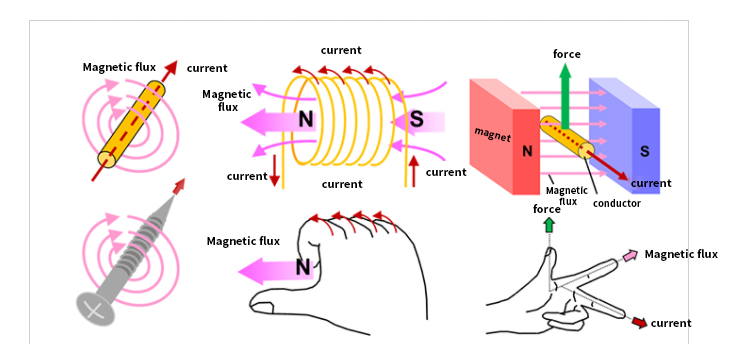
How does the motor rotate? 1) the motor rotates with the help of magnets and magnetic force. Around a permanent magnet with a rotating shaft, ① rotate the magnet (to generate a rotating magnetic field), ② according to the principle that different poles of the N pole and the S pole attract and the same level repel, ③ the magnet with a rotating shaft will rotate.
The current flowing in the wire causes a rotating magnetic field (magnetic force) around it, so that the magnet rotates, which is actually the same action state as this.

In addition, when the wire is wound into a coil, the magnetic force is synthesized, forming a large magnetic field flux (magnetic flux), resulting in an N-pole and an S-pole. In addition, by inserting the iron core into the coil-shaped conductor, the magnetic field lines become easy to pass through and can generate stronger magnetic force. 2) Actual rotating motor Here, as a practical method of rotating electric machine, the method of manufacturing rotating magnetic field by using three-phase AC and coil is introduced. (Three-phase AC is an AC signal with a phase interval of 120.) The coils wound around the iron core are divided into three phases, and U-phase coils, V-phase coils and W-phase coils are arranged at intervals of 120. The coils with high voltage generate N poles, and the coils with low voltage generate S poles. Each phase changes according to a sine wave, so the polarity (N pole, S pole) generated by each coil and its magnetic field (magnetic force) will change. At this time, just look at the coils that generate N poles, and change them in order of U-phase coil →V-phase coil →W-phase coil →U-phase coil, thus rotating. Structure of small motor The following figure shows the general structure and comparison of stepping motor, brushed DC motor and brushless DC motor. The basic components of these motors are mainly coils, magnets and rotors. In addition, due to different types, they are divided into coil fixed type and magnet fixed type.
Here, the magnet of the brush DC motor is fixed on the outside, and the coil rotates on the inside. The brush and commutator are responsible for supplying power to the coil and changing the current direction. Here, the coil of the brushless motor is fixed on the outside and the magnet rotates on the inside. Due to the different types of motors, their structures are different even if the basic components are the same. It will be explained in detail in each part. Brushed motor Structure of brush motor The following is the appearance of the brushed DC motor often used in the model, and the exploded schematic diagram of the ordinary two-pole (two magnets) three-slot (three coils) motor. Perhaps many people have the experience of disassembling the motor and taking out the magnet. It can be seen that the permanent magnet of the brush DC motor is fixed, and the coil of the brush DC motor can rotate around the inner center. The fixed side is called “stator” and the rotating side is called “rotor”.
Rotating principle of brush motor ① Rotate counterclockwise from the initial state Coil A is at the top, connecting the power supply to the brush, and let the left side be (+) and the right side be (-). A large current flows from the left brush to the coil A through the commutator. This is a structure in which the upper part (outside) of the coil A becomes the S pole. Since 1/2 of the current of coil A flows from the left brush to coil B and coil C in the opposite direction to coil A, the outer sides of coil B and coil C become weak N poles (indicated by slightly smaller letters in the figure). The magnetic field generated in these coils and the repulsion and attraction of magnets make the coils rotate counterclockwise. ② further counterclockwise rotation. Next, it is assumed that the right brush is in contact with two commutators in the state that the coil A rotates counterclockwise by 30 degrees. The current of the coil A continuously flows from the left brush to the right brush, and the outer side of the coil keeps the S pole. The same current as the coil A flows through the coil B, and the outside of the coil B becomes a stronger N-pole. Since both ends of coil C are short-circuited by brushes, no current flows and no magnetic field is generated. Even in this case, it will be subjected to the force of counterclockwise rotation. From ③ to ④, the upper coil continuously receives the force moving to the left, and the lower coil continuously receives the force moving to the right, and continues to rotate counterclockwise. When the coil rotates to ③ and ④ every 30 degrees, when the coil is located above the central horizontal axis, the outer side of the coil becomes S pole; When the coil is located below, it becomes N pole, and this movement is repeated. In other words, the upper coil is repeatedly subjected to a force moving to the left, and the lower coil is repeatedly subjected to a force moving to the right (both counterclockwise). This causes the rotor to always rotate counterclockwise. If the power supply is connected to the opposite left brush (-) and right brush (+), a magnetic field with opposite directions will be generated in the coil, so the direction of the force applied to the coil is also opposite, turning clockwise. In addition, when the power supply is disconnected, the rotor of the brush motor will stop rotating because there is no magnetic field to keep it rotating. Three-phase full-wave brushless motor Appearance and structure of three-phase full-wave brushless motor

Internal structure diagram and equivalent circuit of coil connection of three-phase full-wave brushless motor Next is the schematic diagram of the internal structure and the equivalent circuit diagram of the coil connection. The internal structure diagram is a simple example of a 2-pole (2 magnets) 3-slot (3 coils) motor. It is similar to the brush motor structure with the same number of poles and slots, but the coil side is fixed and the magnet can rotate. Of course, there is no brush. In this case, the coil adopts Y-connection method, and the semiconductor element is used to supply current to the coil, and the inflow and outflow of current are controlled according to the position of the rotating magnet. In this example, a Hall element is used to detect the position of the magnet. The Hall element is arranged between the coils, and detects the generated voltage according to the magnetic field strength and uses it as position information. In the image of FDD spindle motor given earlier, it can also be seen that there is a Hall element (above the coil) between the coil and the coil to detect the position. Hall element is a well-known magnetic sensor. The magnitude of magnetic field can be converted into the magnitude of voltage, and the direction of magnetic field can be represented by positive and negative.
Rotating principle of three-phase full-wave brushless motor Next, the rotation principle of the brushless motor will be explained according to steps ① ~ ⑥. For easy understanding, the permanent magnet is simplified from circular to rectangular here. ① In the three-phase coil, let the coil 1 be fixed in the 12 o’clock direction of the clock, the coil 2 be fixed in the 4 o’clock direction of the clock, and the coil 3 be fixed in the 8 o’clock direction of the clock. Let the N pole of the 2-pole permanent magnet be on the left and the S pole be on the right, and it can rotate. A current Io flows into the coil 1 to generate an S-pole magnetic field outside the coil. The Io/2 current flows from the coil 2 and the coil 3 to generate an N-pole magnetic field outside the coil. When the magnetic fields of coil 2 and coil 3 are vector-synthesized, an N-pole magnetic field is generated downward, which is 0.5 times the size of the magnetic field generated when current Io passes through one coil, and when added to the magnetic field of coil 1, it becomes 1.5 times. This will produce a composite magnetic field with an angle of 90 relative to the permanent magnet, so the maximum torque can be generated and the permanent magnet rotates clockwise. When the current of the coil 2 is reduced and the current of the coil 3 is increased according to the rotation position, the resultant magnetic field also rotates clockwise, and the permanent magnet also continues to rotate. ② When rotated by 30 degrees, the current Io flows into the coil 1, so that the current in the coil 2 is zero, and the current Io flows out of the coil 3. The outer side of the coil 1 becomes an S pole, and the outer side of the coil 3 becomes an N pole. When the vectors are combined, the magnetic field generated is √3(≈1.72) times that generated when the current Io passes through a coil. This will also produce a resultant magnetic field at an angle of 90 with respect to the magnetic field of the permanent magnet, and rotate clockwise. When the inflow current Io of the coil 1 is reduced according to the rotation position, the inflow current of the coil 2 is increased from zero, and the outflow current of the coil 3 is increased to Io, the resultant magnetic field also rotates clockwise, and the permanent magnet continues to rotate. Assuming that each phase current is sinusoidal, the current value here is io× sin (π 3) = io× √ 32. Through vector synthesis of magnetic field, the total magnetic field is (√ 32) 2× 2 = 1.5 times of the magnetic field generated by a coil. ※. When each phase current is sine wave, no matter where the permanent magnet is located, the magnitude of the vector composite magnetic field is 1.5 times of the magnetic field generated by a coil, and the magnetic field forms a 90-degree angle with respect to the magnetic field of the permanent magnet. ③ In the state of continuing to rotate by 30 degrees, current Io/2 flows into coil 1, current Io/2 flows into coil 2, and current Io flows out of coil 3. The outer side of the coil 1 becomes the S pole, the outer side of the coil 2 becomes the S pole, and the outer side of the coil 3 becomes the N pole. When the vectors are combined, the magnetic field generated is 1.5 times that generated when the current Io flows through a coil (the same as ①). Here, a synthetic magnetic field with an angle of 90 degrees relative to the magnetic field of the permanent magnet will also be generated and rotated clockwise. ④~⑥ Rotate in the same way as ① ~ ③. In this way, if the current flowing into the coil is continuously switched according to the position of the permanent magnet, the permanent magnet will rotate in a fixed direction. Similarly, if the current flows in the opposite direction and the synthetic magnetic field is reversed, it will rotate counterclockwise. The following figure shows the current of each coil in each step from ① to ⑥. Through the above introduction, we should be able to understand the relationship between current change and rotation. stepmotor Stepping motor is a kind of motor that can control the rotation angle and speed synchronously and accurately with pulse signal. Stepping motor is also called “pulse motor”. Stepping motor is widely used in the equipment that needs positioning because it can realize accurate positioning only through open-loop control without using position sensor. Structure of stepping motor (two-phase bipolar) In the appearance examples, the appearances of HB (hybrid) and PM (permanent magnet) stepping motors are given. The structure diagram in the middle also shows the structure of HB and PM. Stepper motor is a structure with fixed coil and rotating permanent magnet. The conceptual diagram of the internal structure of stepping motor on the right is an example of PM motor using two-phase (two groups) coils. In the basic structure example of stepping motor, the coil is arranged on the outside and the permanent magnet is arranged on the inside. In addition to two phases, there are many types of coils with three phases and five equal phases. Some stepping motors have other different structures, but in order to introduce their working principles, this paper gives the basic structure of stepping motors. Through this article, I hope to understand that the stepping motor basically adopts the structure of coil fixation and permanent magnet rotation. Basic working principle of stepping motor (single-phase excitation) The following uses to introduce the basic working principle of stepping motor. ① Current flows in from the left side of the coil 1 and out from the right side of the coil 1. Do not let current flow through coil 2. At this time, the inside of the left coil 1 becomes N, and the inside of the right coil 1 becomes S.. Therefore, the middle permanent magnet is attracted by the magnetic field of the coil 1, and stops in the state of the left side S and the right side N.. ② Stop the current in coil 1, so that the current flows in from the upper side of coil 2 and flows out from the lower side of coil 2. The inner side of the upper coil 2 becomes N and the inner side of the lower coil 2 becomes S.. The permanent magnet is attracted by its magnetic field and stops rotating 90 clockwise. ③ Stop the current in coil 2, so that the current flows in from the right side of coil 1 and flows out from the left side of coil 1. The inside of the left coil 1 becomes S, and the inside of the right coil 1 becomes N.. The permanent magnet is attracted by its magnetic field, and rotates clockwise for another 90 degrees to stop. ④ Stop the current in the coil 1, so that the current flows in from the lower side of the coil 2 and flows out from the upper side of the coil 2. The inside of the upper coil 2 becomes S, and the inside of the lower coil 2 becomes N.. The permanent magnet is attracted by its magnetic field, and rotates clockwise for another 90 degrees to stop. The stepping motor can be rotated by switching the current flowing through the coil in the above order from ① to ④ through the electronic circuit. In this example, each switch action will rotate the stepping motor by 90. In addition, when the current continuously flows through a certain coil, it can keep the stop state and make the stepping motor have the holding torque. By the way, if the current flowing through the coil is reversed, the stepper motor can be rotated in the opposite direction.
