
Installing an air compressor is not a matter of finding an empty corner and connecting power. A poorly installed compressor runs hot, cycles excessively, consumes more energy than necessary, and fails years before its design life. Industry service data consistently shows that a significant portion of premature compressor failures trace back to installation errors—not manufacturing defects.
This article covers the five installation decisions that determine whether a compressor performs reliably or becomes a maintenance burden: location, ventilation, electrical supply, receiver tank placement, and piping layout.
Why Location Is Critical
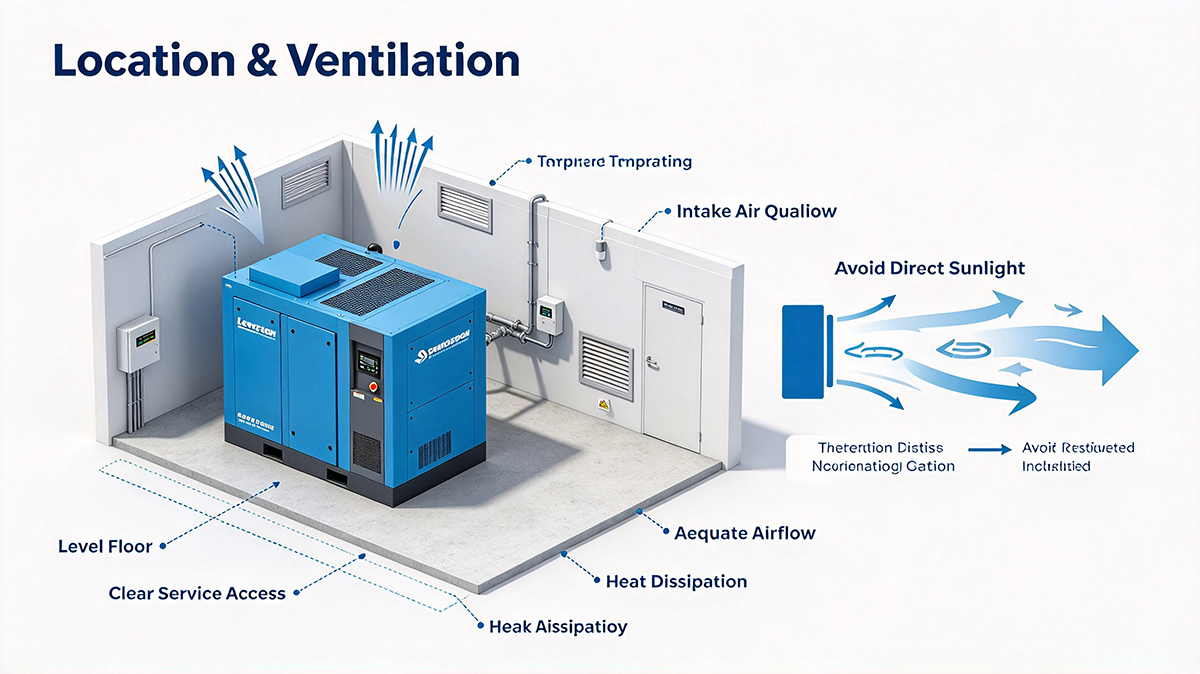
The location determines how well the compressor cools, how easily it can be serviced, and how long it lasts.
Clearances and Access
The compressor needs space for airflow and maintenance access. A common minimum is three feet (about one meter) on all sides of the compressor, with additional space for larger machines or where overhead lifting equipment may be needed . For rotary screw units, manufacturer manuals often specify 48 inches (1,220 mm) at the front and back, 48 inches at the sides, and 5 feet above the unit .
Floor and Foundation
Most rotary screw compressors do not require special foundations—they can sit directly on a level concrete floor capable of bearing the weight . The floor should be flat; for oil-flooded rotary screw units, deviation should not exceed 1/8 inch per 10 feet . Piston compressors, with their reciprocating motion, may require vibration isolation or a reinforced pad.
Environment
Avoid locations where the compressor draws in dust, corrosive vapors, or exhaust fumes. A clean, dry, and cool area is the baseline. Ambient temperature should remain within the manufacturer’s range—typically 10°C to 40°C (50°F–104°F) for many industrial units . Below freezing risks condensate freezing; above 40°C accelerates oil degradation.
Ventilation Is Not Optional
A compressor converts most of its electrical input into heat. A 100 HP compressor produces roughly 250,000 BTU per hour of heat that must be removed from the room . Without adequate ventilation, that heat recirculates, raising ambient temperature and forcing the compressor to run hotter than designed.
Natural vs Forced Ventilation
For compressors 25 HP or smaller, natural ventilation may be sufficient in a well-sized room . Larger compressors, or smaller rooms, require forced ventilation—an exhaust fan sized to remove the heat load. As a rule of thumb, if the room temperature rises more than 5°C above outside ambient, forced ventilation is needed.
Airflow Direction
Position the hot air exhaust and the cool air intake on opposite or adjacent walls—never the same wall. This prevents hot exhaust from being drawn back into the compressor intake . If ducting is used, ensure the duct pressure drop does not exceed the fan’s capability.
Intake Air Quality
The compressor draws in whatever is in the room. If the room contains dust, paint overspray, or solvent vapors, those contaminants enter the compression chamber and the lubricant. Locating the intake away from contamination sources extends filter life and maintains air quality.
Electrical Requirements
Electrical errors are among the most expensive installation mistakes. They can destroy a motor or VSD within minutes of startup.
Voltage Matching and Tolerance
The supply voltage must match the compressor nameplate rating. The actual operating voltage should be within ±10% of the nameplate value . Undersized wiring or excessive voltage drop causes the motor to draw higher current, overheat, and fail prematurely.
Grounding and Protection
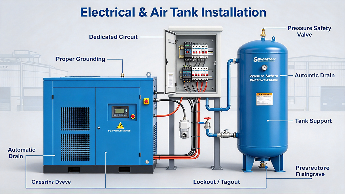
The compressor must be properly grounded according to local electrical codes . A dedicated circuit with an appropriately sized breaker or fuse is required. For maintenance safety, a dedicated switch disconnector fuse (SDF) mounted within sight of the compressor allows isolation without shutting down other equipment .
Phase Sequence and Rotation
For three-phase units, verify motor rotation direction before full operation. Incorrect rotation can damage the compressor and cause oil eruption from the inlet. Check rotation by briefly starting and stopping the motor—less than one revolution—and confirm the direction matches the arrow on the compressor housing .
VSD Considerations
Variable speed drive compressors require a symmetrical three-phase supply—phase angles and voltages must be balanced. Imbalanced supply can cause the VSD to fault or operate inefficiently .
The Role of the Air Receiver Tank
The receiver tank is not just storage. It performs three functions: equalizing pressure variations from compressor cycling, storing air volume to buffer demand fluctuations, and collecting condensate after the compressor .
Correct Placement in the System
The primary receiver should be located after the aftercooler but before filtration and drying equipment . This sequence allows the tank to cool the air and drop out bulk moisture before the air reaches the dryer, reducing the dryer’s load. Placing the dryer before the tank forces the dryer to handle hot, saturated air directly—reducing its efficiency and lifespan.
Sizing Considerations
There is no single universally accepted sizing formula, but common rules of thumb include 1 gallon per ACFM or 4 gallons per compressor horsepower . Some sources suggest 3–5 gallons per CFM depending on compressor type and application . The tank must be large enough to provide a useful pressure band—if the compressor cuts out and cuts in at nearly the same pressure, the tank provides no buffer.
Secondary Receivers
For systems with large intermittent air consumers located far from the compressor room, a secondary receiver placed near the point of use can stabilize local pressure and reduce the impact of demand spikes on the entire system .
Correct Piping Layout
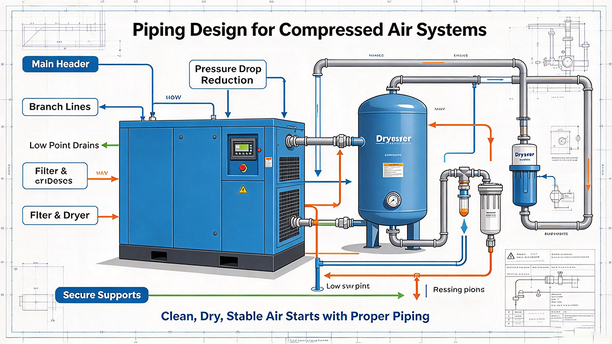
Piping is the delivery system. Poor piping design creates pressure drop that wastes energy and starves tools of air.
Pipe Sizing
Undersized piping is a common and costly mistake. The pipe diameter must be large enough to keep pressure drop below an acceptable limit—typically 0.1 bar (1.5 psi) or less from compressor to point of use . Smaller pipes increase air velocity, which increases friction and pressure loss. If in doubt, go larger.
Material Selection
Aluminum is the preferred material for compressed air piping: lightweight, corrosion-resistant, and easy to modify. Galvanized steel is acceptable but heavier and harder to install. Avoid PVC—it shatters under pressure and is not approved for compressed air. Copper is effective but expensive. Older iron pipes corrode internally, restricting flow over time .
Slope and Drainage
Install horizontal piping with a slope of 1–2% toward drain points, and install automatic drain valves at low points . Condensate collects in low spots; without drainage, it accumulates and eventually gets pushed into tools or processes.
Branch Connections
Connect branch lines from the top of the main header, not the bottom. This prevents condensate from flowing into branch lines . A drip leg—a vertical section with a drain—at the base of each branch provides additional protection.
Loop Layout
For facilities with multiple consumption points, a closed-loop (ring) piping layout provides more uniform pressure and allows sections to be isolated for maintenance without shutting down the entire system .
Key Takeaways
| Installation Area | Critical Requirement |
|---|---|
| Location | Level floor, 1 m clearance, clean and cool environment |
| Ventilation | Remove heat; forced ventilation for >25 HP or small rooms |
| Electrical | Match nameplate voltage (±10%), proper grounding, verify rotation |
| Receiver tank | After aftercooler, before dryer; size for pressure band |
| Piping | Oversized rather than undersized, sloped for drainage, top-connected branches |
FAQ
Q1: Do I need a special foundation for my compressor?
Most rotary screw compressors do not. They can sit on a level concrete floor capable of bearing the weight . Piston compressors may require vibration isolation or a reinforced pad due to reciprocating motion.
Q2: How much ventilation does a compressor room need?
If the room temperature rises more than 5°C above outside ambient, forced ventilation is required. For compressors above 25 HP, natural ventilation is usually insufficient . Size the exhaust fan to remove the heat load—roughly 2,500 BTU per horsepower per hour .
Q3: Where should the receiver tank be installed?
After the aftercooler and before the dryer. This allows the tank to cool the air and drop out bulk condensate before the air reaches the dryer, reducing the dryer’s load .
Q4: What size piping should I use?
Size for a pressure drop of 0.1 bar or less from compressor to point of use. When in doubt, choose the next larger size. Undersized piping is a common cause of pressure loss and energy waste .
Q5: Can I use PVC pipe for compressed air?
No. PVC shatters under pressure and is not approved for compressed air service. Use aluminum, galvanized steel, or copper.